I don't have techno-fear--I have techno JOY!!! --Eddie Izzard.

Monday, June 19, 2006

Orsay: efficiency for our actual detector configuration; also online diagnostics

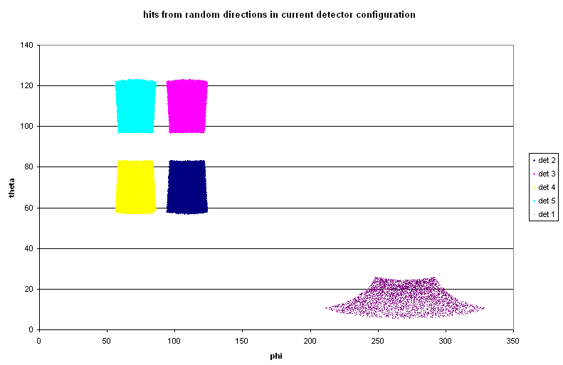
First step: check that my geometry routine is giving sensible results. Give it the detector locations as input, and see how many randomly-generated directions result in a hit. In this way we can also deduce that the detectors cover 7% of the total solid angle.
Detector locations:
"rd={110,110,110,110,150}
thetad={70,110,70,110,15}
phid={109,109,71,71,270}"


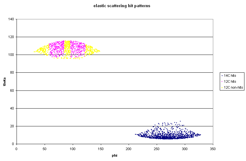
Next step: use the same code (forget about energy loss in the target for now) to see where elastic scattering events hit--both 14C and 12C ejected from target. Just like we see online, most of the 14C hits are at forward angles in detector 1, and the corresponding 12C are in detectors 2 and 4 only.
The thing to note here is that the cross section function used here is purely rutherford--the angular distribution has no "wibbles" in it, to use an Alex-ism.


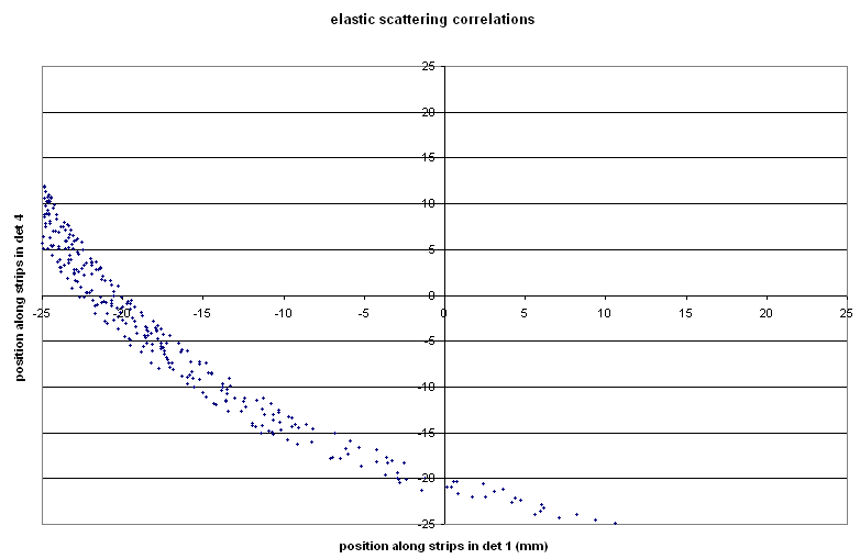
Now try also reproducing the plots of position in det 1 vs position in det 4: Here we get a smooth curve, whereas online there are two clumps. Either the "wibbles" are making their presence felt, or we're seeing reactions or something in addition to elastic scattering.


Now for reaction: 80 MeV 14C on 50 μg/cm2 12C: take into account beam spot size, energy loss/straggling in target and dead layer of detector. Hit pattern:
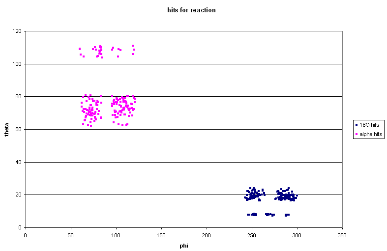


The gaps between the "quad" detectors mean that there are gaps in the "good" 18O hit pattern in detector 1.

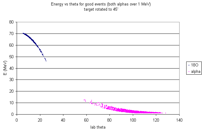
Here's the energy vs. theta plot, too:


Note that both of these "reaction" plots are for good events only, i.e. for events for which the 18O and both alphas are detected and have energies such that the signals at both ends of the strip are above 500 keV. The good events are a small fraction of the total events: 156 total good detector hits for 93180 simulated decays.
10260 O hits; 9825 O hits above threshold
173 alpha hits above threshold
-->0.2% efficiency for good events, although 10.5% efficiency for 18O.

Update: If we move two detectors to 90', we'd get 0.8% efficiency! All we'd have to do is move one mount to 90' on the circular mount, and remove the unused detectors. It would certainly be worth doing this if we're going to run with only two detectors.

Here's the theta and phi ranges of the current quad configuration, together with real 18O hits and potential matching alphas. You can see that most of the potential alphas fall in the gaps between detectors.

Thursday, June 15, 2006

Orsay: and now, the bad news

Not to be a total downer or anything...

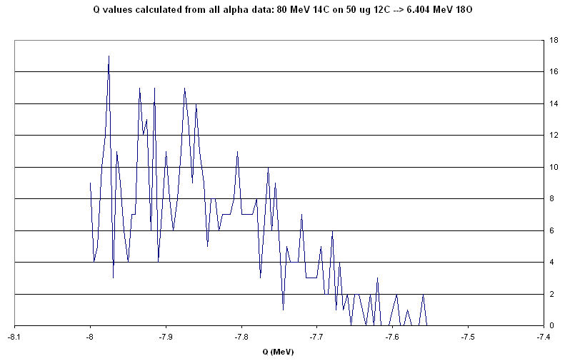
I've been struggling with my beloved simulations over the past couple of days. I'm not bright enough to figure out exactly why they keep crashing. Crashes notwithstanding, this is my best guess at the distribution of Q values we might expect to get from the resonance we want to populate.

What it includes:
beam spot size, granularity of angles calculated from detector position, all energy losses/straggling and angular straggling in target, energy loss/straggling in detector dead layer, cross section for reaction (correct this time!) with the resulting angular distribution of particles.

What it doesn't include:
any spread in beam energy, whether all particles hit the detectors (I sorta faked the detector effects by assuming all particles go through a dead layer straight-on and have their angular information degraded by a given amount)--so it doesn't give any information about our total efficiency. (this is the part that frustrates me--right now I can't figure out why I can't get the geometric part of the code to work right: it should say whether or not all of the particles hit the detectors and whether the energy signals on both ends are over threshold--but so far it's just crashing. grr.)

With those caveats, this is what the Q value distribution should look like.


Ew. This isn't what we were counting on when we were planning the experiment.

Monday, June 12, 2006

Sunday, June 11, 2006

Orsay: emergency cross section calculations!


same as above--this time exclude alphas at forward angles: this means that all 18O fall within 5-11'. alphas are really close to the threshold.


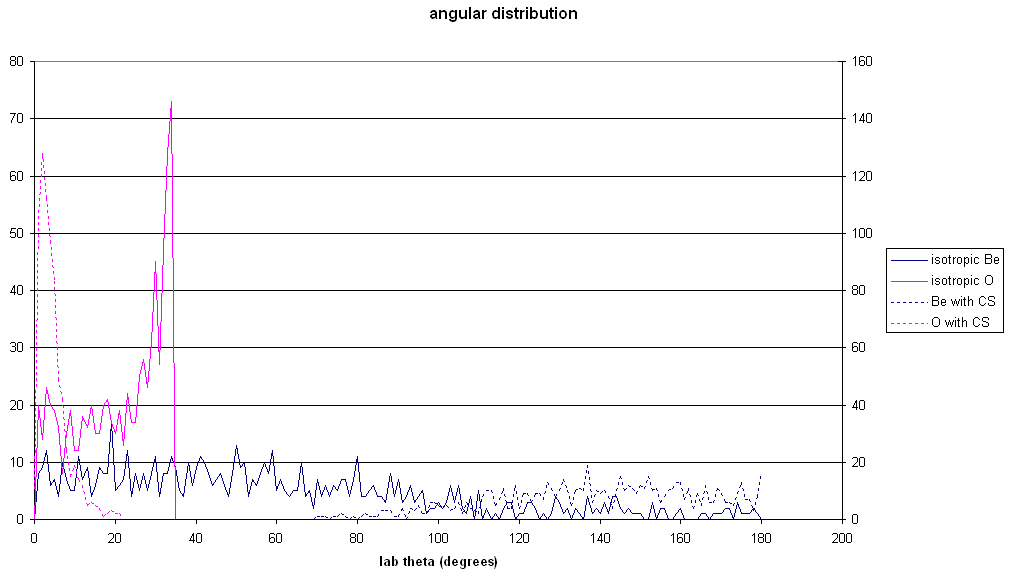
angular distribution for isotropic 18O & 8Be, then with the cross section function applied to 18O's cm angle.


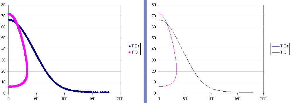
...comparing kinematic results from simulation and jrelkin calculation


...and an energy-angle plot for 18O and 8Be, with the cross section applied: to be compared to the plot directly above: all the low-angle 8Be events go away.

17O (p,α) proposal: simulations including energy loss in gas and position of reaction

Here's the results of a simulation that (sort of) takes into account the width of the resonance and the energy loss in the gas.
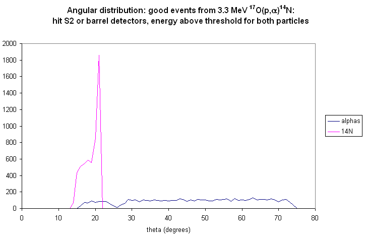
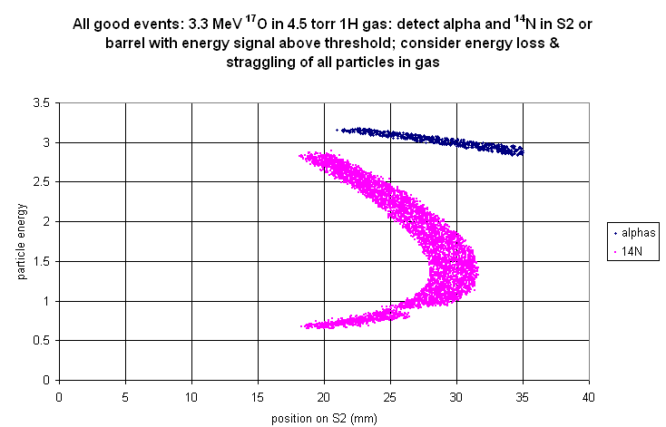
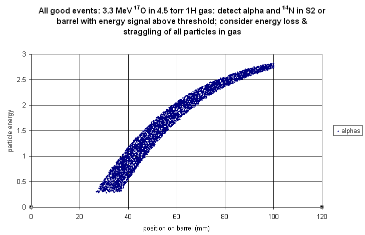
Assume the reaction takes place within the first centimetre of gas. The S2 is positioned 83 mm downstream from the beginning of the gas cell, and the barrel is cylindrically symmetric at 40 mm from the beamline. The beam has a radius of 1 mm. Energy loss, energy straggling, and angular straggling of the beam before the reaction position are taken into account, using straggling parameters derived from SRIM. The energy loss and straggling of the reaction products through the gas and dead layer are taken into account, but I couldn't figure out how to do the angular straggling through the gas. The dead layer thickness is assumed to be like normal detectors--0.8 μm--but we may end up using thick-deadlayer detectors to compensate for the brightness in the chamber. The energy loss in the deadlayer is significant, particularly for the high-angle protons, so thick deadlayers might actually mean a decrease in efficiency.
what else. I think that's the main parts of the simulation. Here's the results.

E vs. theta for alphas and 14N


angular distributions of just the good events


radius in S2 for both particles for good events


front-back position on the barrel (100 mm is forward, 0 mm is ~100')


Next up: rate calculations, and energy loss simulations for elastically scattered protons.

Friday, June 09, 2006

17O(p,α) proposal: detector positions and efficiency

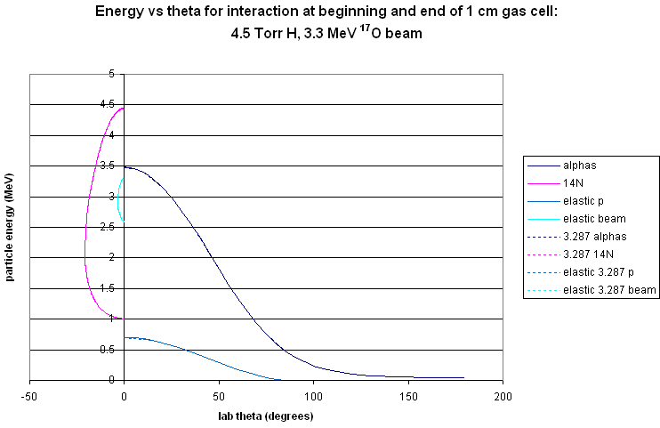
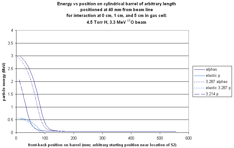
These are just relkin calculations for 3.3 MeV 17O on a 4.5 Torr H gas target. I make the energy loss over 1 cm of target to be 13 keV. I did the kinematics for the reaction and the elastic scattering at the beginning and end of that range (i.e. 3.3 MeV at 0 cm, 3.287 MeV at 1 cm). The figures are
1. an e vs theta plot: the particle energies (neglecting energy loss/straggling of products in target and in dead layers) vs the real god-given particle angles (again obviously neglecting angular straggling in the target). The lines for the same reaction at the two positions lie practically on top of each other.
2. an e vs S2 position plot. I put an S2 at 91 mm downstream from the 0 cm position, and calculated the radial position of the particles on it, if they hit it. (The position was chosen to maximize the number of 14N we catch: we throw away about 25% of the small-angle 14N with this position, but we'd have to throw away 5% anyway, and it may turn out that this is the optimal position.)
3. an e vs "barrel" position plot. I put a cylindrical barrel of arbitrary length at a radial distance of 40 mm from the beam line, with a starting position somewhere near the S2 (position increases upstream in this plot, so something going off from 0 cm at 90' would be at ~100 mm on the barrel).

Next step: figure out what this means: by detecting the alpha and 14N in some sort of configuration like this, can we deduce the centre of mass energy?

Comment from Tom: putting an S2 inside the dragon gas cell would indeed involve making a new target box. (We're cunning like that.)

A note on efficiency: with an S2 positioned as indicated, we catch 75% of the 14N from the reaction at the 0 cm position. With a 10 cm long cylindrical barrel detector, we catch 82% of the alphas, with an additional 10% going into the S2. The total efficiency is then about 71%. If the barrel detector has less than 100% coverage over its angular range, the efficiency will be decreased by a corresponding amount--for example 50% coverage (like we might get with two rectangular detectors if we were very cunning) leads to 35% total efficiency, whereas with four we might get about 60% total efficiency.

A further note on the figures: the ones I've just uploaded include the effects of reactions at 5 cm as well as at 0 and 1 cm--just to see.


Wednesday, May 31, 2006

Orsay: detector configuration: reality intervenes

It turned out not to be feasible to use the Deep Space 9 mount after all. Instead, we're going to use the circular mount. Detectors are mounted on L-shaped brackets, which are put at any θ with respect to the beam line (defined from the centre of the detector) and at radial distances ranging from ~10 to ~18 cm. It's easy to mount up to four detectors in plane (i.e. φ=0 or 180), but mounting detectors out of plane will take some work.
That's reality check 1. Reality check 2 is that there just aren't enough amplifiers to go around, if we are planning to use 6 detectors. Stick with 4!
As it happens, the only feasible way to mount 6 detectors on this mount would give us less solid angle and fewer total good events than the best way of mounting four detectors. The best arrangement of four detectors I've come up with has a coverage of 7.5% solid angle, compared with 6.7% for the best feasible arrangement of six detectors.
(Both of these arrangements take into consideration the fact that we can't get closer than 5' or 1.5 cm from the beamline without frying the detectors.)

Here's the outlines of the positions of the four detectors...


...and the reaction hit patterns...


Next up: how we're actually going to mount the detectors in this configuration....

Saturday, May 27, 2006

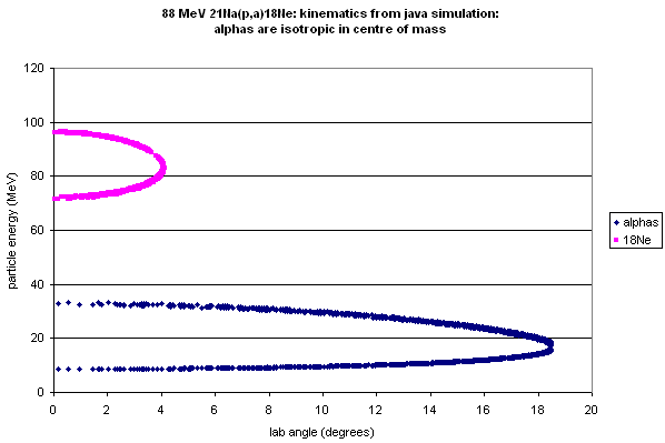
by special request: 21Na(p,α)18Ne

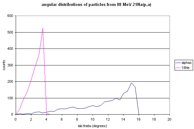
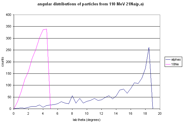
Simple simulation: take 110 or 88 MeV 21Na beam energy, 350 μg/cm2 CH2 target. Find angular distributions of both α and 18Ne; what's the detection efficiency with an S2 and another detector (poss. ionization chamber or some sort of silicon)?

I'm assuming isotropic distribution of the alpha particles in the centre of mass. This involves making a very inelegant--but reasonably accurate--transformation from c.m. to lab frames. At some point I'll fix this. Maybe. :-)

I'm also neglecting the effect of the size of the beam spot and all effects of the detectors themselves (energy straggling in the dead layer; granularity of calculated angle due to strip width...)

Here's the kinematic results for the two energies...


and the angular distributions of the particles...


If two S2 detectors are used for the 110 MeV experiment, positioned at 103.4 mm and 333 mm, they catch 1482 of 1834 simulated events (both alpha and 18Ne hit a detector for a given event). 1818 of the 1834 alphas are caught, but only 1482 of the 18Ne: the ones emitted at the smallest angles still escape.

Thursday, May 25, 2006

17O (p,α) proposal

Investigating the possibility of putting DSSSDs in the Dragon gas target...will we be able to reconstruct the centre of mass energy from the measured α and 14N energies and positions?

With a beam energy of 3.3 MeV, we populate only the ground state of 14N, since the first excited state is just above 2 MeV and the Q value is only +1.2 MeV.

Do kinematic calculation (JRelkin) for forward angles, for 3.3 and 3 MeV beam energy (assuming 300 keV energy loss in gas for the second case). Arbitrarily choose reaction positions of 10 and 8 cm upstream of the detectors. (Pretend the system has cylindrical symmetry for now...add the complication of the real detector geometry later on.) Then see what measured position the real thetas would give, and what information we can glean...

Here's the particle energies vs. the real thetas...


...and the particle energies vs. the measured radial position...


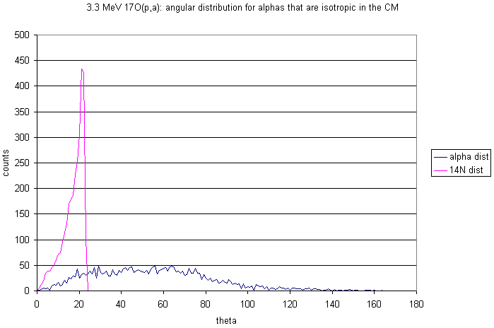
And here's the angular distribution of the outgoing alphas and 14N:

Wednesday, May 17, 2006

Orsay: cross sections for various beam energies using FRESCO

I blatantly ripped off Kelly's input file for 14C(12C,8Be): I changed only the order of the target and ejectile parameters in the 7th line--I may have left something out. Assuming that everything's okay, the results are encouraging: the peak of the total cross section is still at a beam energy of 80 MeV.

cross section

The angular distribution loooks different now. I don't think Kelly's results had a minimum at 25 MeV, and I also remember there being a couple of orders of magnitude difference between max and min....

80 MeV cs

Am I doing something wrong?

Orsay: trying to not fry the detectors

so here's the latest version of the configuration: forward in-plane detectors at r = 150 mm and theta = 15'; backward in-plane detectors at r = 130 mm, theta = 37' (phi = 0,180'); out-of-plane detectors at r = 100 mm, theta = 27' (phi=90,270').

I think this is the best we can do: it's simple to add spacers to the Deep Space 9 mount to move four of the detectors forward, and it avoids putting the detectors at angles smaller than 5' where they would meet a speedy death.

The on-axis strips of the forward in-plane detectors will live for 10.4 days, assuming a 2 pnA beam current and 1e9 elastic events to kill them.

Hit pattern for reaction:

modDS9 rxn hits

and especially for Alex, schematic drawings of the positions:

IP schematic

OOP schematic

Tuesday, May 16, 2006

Orsay: how to predict detector damage?

So here's what I'm doing about cross sections in the elastic scattering simulation:
  1. Choose a random direction for the outgoing particle (8Be).
  2. Calculate the c.m. theta corresponding to that direction.
  3. Calculate the Rutherford cross section for that angle, normalized to 1 at 5':
    double RCS=Math.pow( Math.sin(theta/2) , -4);
    double cross_section=RCS/276237;
  4. Choose a random number between 0 and 1 ("test").
  5. If "cross_section" is greater than "test" then proceed (with energy loss calculations and direction tests and other assorted nonsense); otherwise discard this event and start again.
Using this approach I get however-many hits per strip, from elastic scattering, for every however-other-many simulated events.

(In a separate calculation, I determined the solid angle for each strip in whatever configuration.)

My question: How do I go from that ratio (and solid angle) to a reasonable estimate of time to damage the detectors?

Other information I have: from Tom's notes:
2.51E+18 atoms/cm2 in target (for 50 ug/cm2 12C target)
1.25E10 particles per second for 2 particle nanoamps
72495.9 mb/sr for elastic scattering at 5'

Someone please tell me how not to be a numpty, and how to combine all this information in a useful way.

Update: I think I might have come up with something.
  1. Use the Rutherford cross section to calculate the number of events, per second of beam time, into annuli of width 1', centred on 1',2',...55'.
  2. Simulate elastic scattering and count how many events go into the same annuli, for a given number of particles on target.
  3. Compare the resulting hits-per-degree curves, and find a normalization coefficient that takes us from "simulated hits per X simulated events" to "hits per second".
  4. Apply the normalization coefficient to the "hits per strip" calculated above.
  5. Deduce the lifetime of each individual strip (i.e. the number of seconds/hours/days for it to get 1e9 hits, with the given beam current).
...I'm too sleepy to go into the gory details right now--maybe tomorrow--but it looks like "configuration 5", my current favourite, will result in the middle half-dozen strips of the detectors that are at lowest angles dying within 5 days. This is good: it gives me another constraint to work with when picking detector positions.

(I figured this out this evening instead of (a) marking the papers I need to hand back first thing tomorrow, (b) working on my Manchester talk, or (c) going to bed early, so maybe I'm still a numpty.)

Orsay: detector configurations AGAIN

I finally got wise and did the high-school geometry necessary to describe the positions of the edges of detectors. Here's what the Deep Space 9 ordinary positions look like...

ds9

...and here's my current favourite configuration, affectionately known as "configuration 5"...

config 5

For both of these, the legend gives the relevant position information: r, theta and phi values for the centre of each detector.

Here's the hit patterns for elastic scattering (using a Rutherford-esque cross section)...

config5 elastic hit pattern

ds9 elastic hit pattern

...and the hit patterns for the reaction...

ds9 hit patterns

config5 hit patterns

Wednesday, May 10, 2006

Orsay: Deep Space 9 mount for PS3Ds

Here's the hit pattern that results from the basic configuration
rd={150,150,150,150,150,150}
thetad={15,37,15,37,27,27}
--that is, all the detectors are at a radial distance of 15 cm; the forward in-plane ones are at theta=15' and the backward in-plane ones have theta=37'; and the out-of-plane detectors are at theta=27'.
In this configuration, there are 1609 hits out of 500 000 events simulated (equivalent to 10477 interactions--so the detectors have an efficiency of 15%.
DS9 basic hit pattern

Modify the configuration: bring the out-of-plane detectors forward by 5 cm.

In this configuration, there are 2093 hits out of 500 000 events simulated (equivalent to 10562 interactions--so the detectors have an efficiency of 20%.

DS9 OOP in hit pattern

Monday, May 08, 2006

Orsay: energy considerations for S2s

Need to consider whether the particles we want to see will punch through the S2 detectors. Here's the energies of the "good" events with the S2 configuration from below:

2s2 e vs theta

Stopping the alphas might be a problem. Here's what SRIM says:...actually the table formatting is too hard to read. Never mind. What it says is that 25 MeV alphas stop in 317 um of Si, and 35 MeV alphas stop in 564 um. Even the Edinburgh 500-micron S2s won't be enough to stop the forward alphas.

(Stopping the Oxygen is not a problem--just a few microns does it.)

Orsay: trying out S2 detectors

Although we don't have LEDAs to burn, we do have S2s, apparently. Try those: at 55 and 190 mm from the target they cover 3.3-32.5' with really high efficiency. The hit pattern is shown below...

2s2 hit pattern

...and the angular distribution of 18O and α hits:
2s2 ang dist

Compare these to the hit patterns and ang dists of one arrangement of 6 ps3ds:
config 4 hit pattern

config 4 ang dist

Advantages of using S2s instead of PS3Ds: Lots of coverage; easy analysis; Q value no less precise; fewer channels of electronics; fewer detectors to fry.

Disadvantages: we have to scramble for pre-amps and cabling and such; and we don't get to use the Deep Space Nine mount.

Thoughts?

Orsay: Why are we using position-sensitive strip detectors, again?

...besides the logistical "that's what we have on hand to fry" reasons, I mean--which in themselves can be pretty compelling.

While poking around looking for the best way to arrange the PSSSD detectors (on which more anon), I got to thinking how nice it would be to have something that gave full coverage at small angles. Then I got to thinking, well, maybe we need the extra-good position resolution that the PS3D detectors provide. Then I figured, hey, why not test that assumption. So here's the results: Q calculated for the 6.404 MeV level in 18O, various different ways: 1. using the true value of θ; 2. using the true values of both θ and φ; 3. using the value of θ that the PS3D gives us; 4. using both θ and φ from the PS3D. (Using θ and φ measured for the alphas you calculate x, y, and z momentum components for the residual nucleus and then use that to calculate its energy and hence Q; using just θ you calculate the parallel (to the beam direction) and perpendicular components of its momentum.)

Q ps3d

What you see is that it makes no difference whether you use φ to calculate Q or not. This suggests that the bad φ resolution of LEDA or S2 detectors wouldn't be a problem. Check it out.

Q leda

When you calculate Q with LEDA/S2 θ information, you get (essentially) the same result as from the PS3Ds, even though if you include φ, the resolution is crap. For comparison, the PS3D θ result is shown on the same plot.

Conclusion: Using concentric-strip detectors in this case doesn't limit the quality of the information we get. There's a chance that it might improve the quantity too. Stay tuned for the next entry...

Monday, May 01, 2006

Orsay: angular distributions for different species

Here's a comparison of alphas and 18O for Ex(180)=6.404 MeV: the distributions for all emitted particles are shown, together with the good and sub-threshold events for the current detector configuration (config C, shown in an entry below)

angular distributions

Orsay: take out delta-E detectors: resulting Q-value distribution

simple Q